
With DCC, I had a workbench decoder tester board with motor for testing new decoders before installation. Has anyone come up with a workbench pre-installation test stand for the LocoFi module? I have just received my pre-ordered Gen 3 decoders. These two modules are slated for installation in a Mehano 2-6-0 and a Bachmann 2-8-0. The installation won’t begin until I have received a new Fischer Stay alive that will be included in the steam installations.
A thought: could I use the same power source/setup used for my NCE PowerCab programming track. I would add temporary alligator clips to the red/black wires and just clip the leads to the programming track. Would I need a motor as well for the module to work?
I did just practice removing the MicroSD card and copying the wav files and testing them in Audacity. They certainly sound more robust than the earlier wav files from the Gen 2 module.
best
Ken Adams
While we are not aware of the wiring associated with a programming track, we believe it should be possible as long as the LocoFi™ module gets DCC power through the red and black wires. Orange and grey wires would feed the motor. White and yellow would connect to the positive of its own LED while the blue would connect to the negative of both the LEDs.
If you have a picture of the setup and a wiring diagram, we may be able to suggest something.
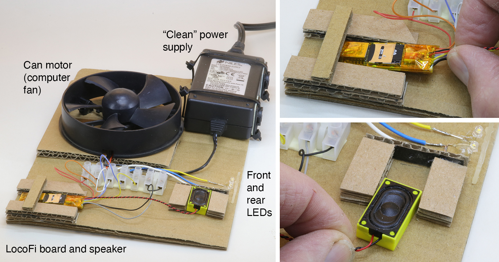
Here’s a way to test your control unit before installation. The base is double-thick corrugated cardboard sized to fit the components. Any old can motor will do to take the place of a loco motor. This one was a computer fan. It was easier to just mount the whole fan instead of taking the motor out and then making something to hold it. The power supply is a leftover from some forgotten piece of computer gear. For electronic control of locos the power supply must be “clean” — don’t try to cheap out by using a regular DC train power pack.
Cut and glue pieces of cardboard to allow the board and speaker to slip in. It’s just to hold them while testing so make it easy to put them in and take them out. I used two LEDs that had a “too cool” color temperature for my modeling era but they’re fine for a test board. Note that the test component wiring colors are the same as used on the control board.
Excellent! It’s especially useful if you have plenty of boards to test. For example, we do. We test out each module before shipping them out to avoid any possible customer disappointment.
Question: What are the plastic tabs that you stick the wires in?
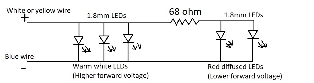
A small note about LEDs (because you mentioned “too cool”). The onboard resistors are appropriate for warm white, blue or white LEDs only whose voltage drop is between the range of 2.7V – 3.3V. The light outputs support a max source current of about 12mA. As such, if someone plans to use red or green LEDs that have a lower voltage drop, the onboard resistors may not be enough and risk overloading the light outputs. In case of those LEDs (e.g. some locos use red LEDs on the rear that are automatically lit when front warm white lights are lit and vice versa), adding an additional 68ohm or so external resistor is recommended in series only for the current path going to them. See example schematic below:
I don’t expect to have a high number of boards to test but I’m just starting to work on editing/loading steam sounds onto the micro SD card to replace the standard diesel sounds so I wanted to test them easily.
The plastic tabs that I stick the LocoFi wires in to connect with the test components go by various names: terminal strip, terminal block, barrier strip, barrier block and connector barrier block to name a few. They all seem to mean the same function. They come in a variety of sizes to fit various wire gauges and numbers of connections per block. I don’t remember where mine came from but it is similar to this one: https://www.digikey.com/en/products/detail/on-shore-technology-inc/ES0800-08DSFB/2720746 . This link is for an 8-wire one but I typically buy several 12-wire ones at a time then cut them to match what I need — in this case I cut it down to a 7-wire.
Thanks for mentioning the differences between LEDs and showing how to accomodate the red and green ones. The LocoFi3 board comes with two pairs of loose white LEDs (one pair white — daylight? and one pair warm white). Since my modeling year is 1939 I favor the warm white LEDs on models to simulate older incandescent bulbs. On this test board I used the white (probably daylight color temperature) ones that look “too cool” for my models.
Yes. Indeed. It should be useful during sound editing as well wherein you may have to take the microSD in/out time and again.
Does your terminal block have screws? While researching for terminal blocks, we came up with another type that could be useful for quick connect/disconnect. We haven’t tried those but look promising. See https://www.amazon.com/dp/B09PMYT9CB
Yes, mine have screws. The lever-type inline splices that you linked look like they would be a better choice. I’ll have to get some for future projects. Thanks!
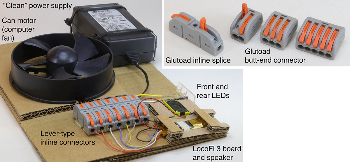
Here’s my revised test board. Those inline splices are perfect for this use. They come as one-wire units and have a mortise-and-tenon shape on each so they can fit together to make as many in a “gang” as you want. They don’t come with any attachment holes so I used double-stick foam tape here.
There are two kinds of Glutoad connectors so be sure that you’re buying the style that you want. The butt-end connectors are terminal strips that have all positions “hot.” Typically, one wire is the input and the others are powered by it. They come in units of of two-, three- and five-wires and do not link together like the inline splices.
I turned the mounting location for the LocoFi board around because it was easier to access the microSD card when the hinge is on the left. I’ve opened and closed it so many times that I broke it so the microSD card is held in place with tape.
Great to hear that the splices were useful! As for the hinge, if only the top part came off without any other broken or bent metal pieces, then it’s easy to put it back on. There’s two latches one on each side that go in the tiny grooves. You should be able to carefully put them back in. Check out this video to see a magnified view that might help: https://www.youtube.com/watch?v=k3_6ZwgniAc&ab_channel=GlobalConnectorTechnology
In case you are unable to repair it, please send it back to us and we can repair/replace it for you at no extra charge. It should still be covered under warranty.
Thank you for your generous offer. Electrically, the board works fine and it just requires a piece of tape to hold the microSD keeper that I damaged in place. So, there is no need to replace it.
