Hello
Have an HO Athearn CF7 & a LocoFi module (see attachments). Given all the wires involved don’t know how all the wires are connected. Too used to plug & play decoders & haven’t hard wired any yet. Have looked on the internet for help but no luck yet. Anyone know of a wiring diagram for this kind of installation? TIA
Andy Jackson
lajrmdlr@gmail.com
CF7
Hello Andy,
Thank you for your message. Please watch the Installation of LocoFi™ – the WiFi sound decoder module in older Athearn Blue Box locomotive that specifically deals with this scenario. Hope it helps.
Best regards,
Admin.
A wiring diagram would be a whole lot easier for me to read than following a long video.
Certainly. Please check out our Quick Start Guide (attached) (this and other guides also available under Resources section of our website) for the wiring diagram.
We still highly recommend watching the video at least once especially if you’ve never done a hard wire install and it’s not a DCC ready locomotive. There’s a section of about 15 minutes @4:00 that explains the wiring as well in the typical Blue Boxes.
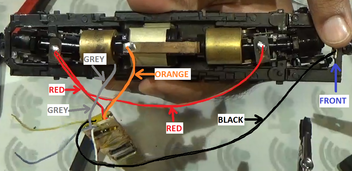
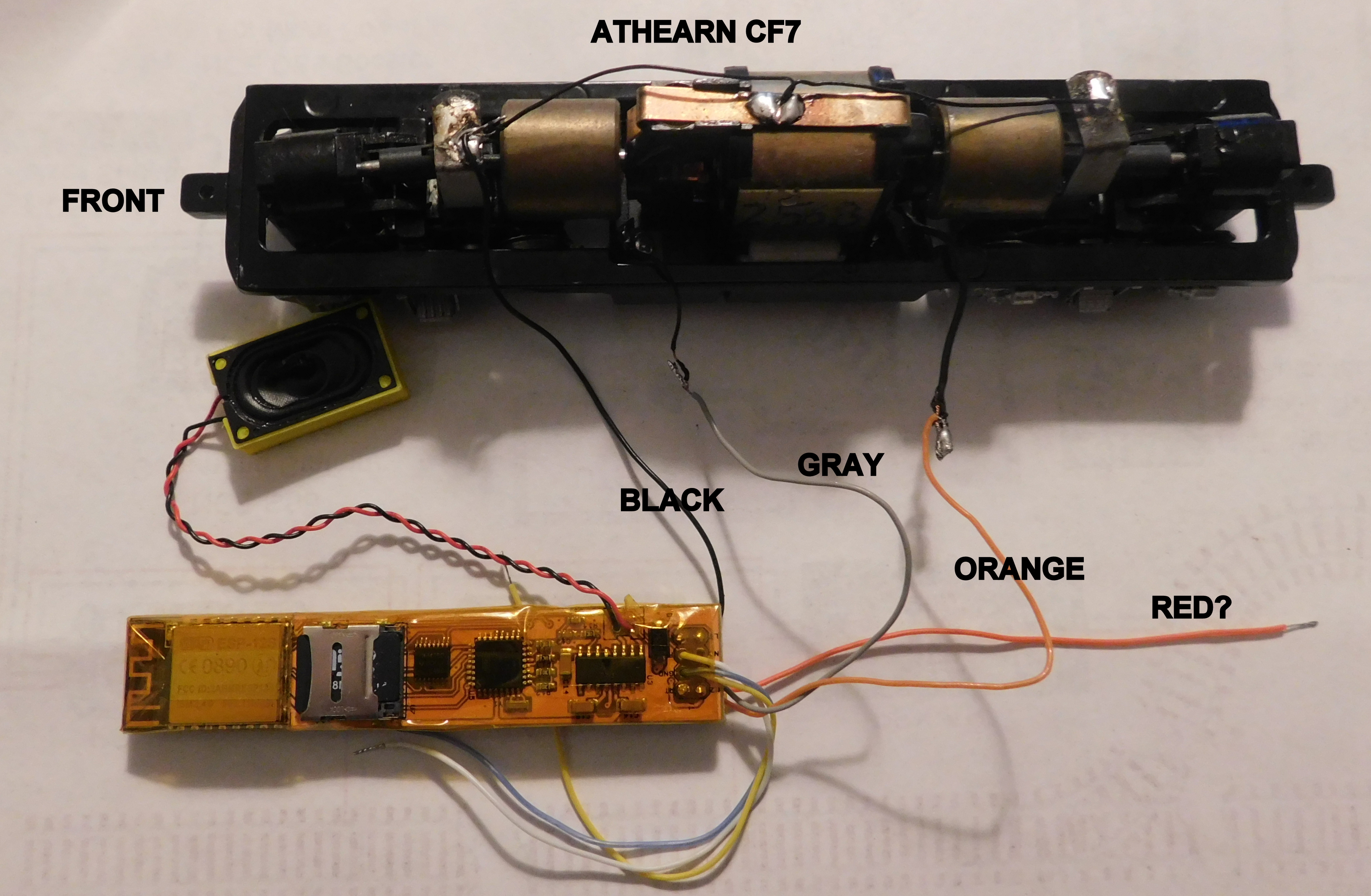
Watched the video but couldn’t follow it, Attached an image of my progress so far. Think the black, gray & orang wires are in the right place, but not sure where the red wire goes. Any help would greatly appreciated
Thank you
And Jackson
No worries. We’re glad that you asked before powering it up. Although it isn’t very clear from the picture but the wiring does seem wrong. It might blow up the module if powered up like this. We’ve prepared two more wiring diagrams to illustrate how it should look inside the actual loco (as opposed to the “wiring diagram”). Key points to observe:
-
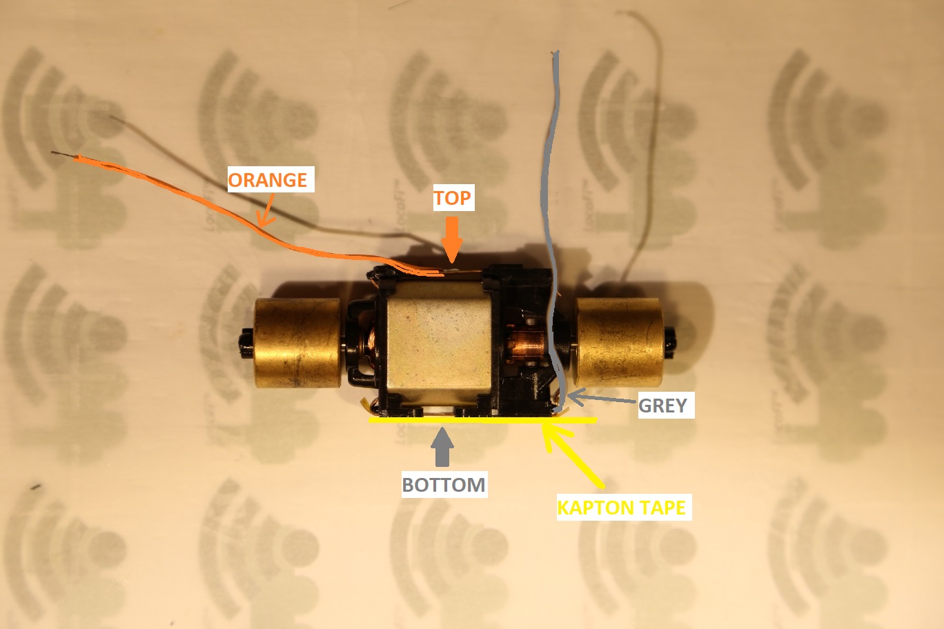
MOTOR ISOLATION is key. The motor wires (orange and grey) should never come in contact with the power supply.
-
The orange connects to the top of the motor while the grey connects to the bottom of the motor.
-
To isolate the frame from the motor bottom where the grey wire is attached, a piece of Kapton or other electrical tape must be placed between the motor bottom metal strip and the frame.
-
The black wire connects to the frame towards the front of the loco.
-
The front and the rear trucks are connected together with a red wire.
Hope this helps.